UNIGINE 2.7 Released
A new version of UNIGINE has just been released.
Updated SDK Editions
SDK editions and prices were updated, detailed information is available at unigine.com.
- UNIGINE 2 Entertainment (previously Starter)
- Enabled custom splash screens
- Added advanced performance profiler
- UNIGINE 2 Engineering (previously Professional):
- Added support for geo-coordinates
- Added Landscape Tool
- UNIGINE 2 Sim is kept as it is (the most complete edition of the SDK)
New Voxel GI Solution
Voxel Probe Lights
Introducing a new GI system which does not require UV layouts for models. So, there’s no need to create UV channels for this purpose anymore. Moreover, creating high-quality UV layouts for the most of the content used in architectural visualization (high-poly models) is a very difficult task.
This solution worked good for our Oil-Refinery demo having a high density of high-poly 3d models, as making UV layout for the whole scene would be next to impossible.
The workflow is as follows:
- Import your content to the Editor,
- Place it on the scene,
- Place a new Voxel Probe Light that enables you to bake global illumination within its volume
- Click Show Bake Lighting specify necessary parameters and click Bake .
That’s it! You’ve got realistic lighting that has very modest hardware requirements doesn’t depend much on screen resolution, works perfectly with multi-monitor setups and even in VR.
The fact that Voxel Probe Light is implemented as a separate object offers you a number of advantages. You can enable/disable it at run time changing the lighting of your scene. You can smoothly blend GI from several Voxel Probes to add more details at certain areas of the scene. Moreover, dynamic objects moving along the walls, for example, will receive GI from them without any extra lights required.
It is very important that this technology works with any object in the scene, be it a decal or a light source (including light volumes), fog, vegetation, or even custom materials, that you create. To simulate a light source you can just enable emission for the object’s material.
In case if your scene requires a dynamic change of lighting during the day-night cycle, you can use the Use Sun Coloroption to enable it.
For more information on baking GI and using Voxel Probes, please follow the links below:
Listed below are the drawbacks and benefits of this technology for various applications.
Benefits
- Gamedev: GI solution that works with both static and dynamic objects. Does not require UV. High performance, working even in VR. Scalable quality, baking for preview or final baking with the highest quality. Easy to use: place the Voxel Probe, click a button, get the result. Any object in the scene can become a light source, just enable emission option for its material.
- Archviz: Does not require UV. Works with high-poly 3D models. Ability to enable/disable lighting per object changing the lighting of the scene (e.g. turning the lights on and off). Ability to bake a large number of GI bounces up to tens of them, increasing the required rendering time just twice. Any object in the scene can become a light source, just enable emission option for its material.
- BIM: Does not require UV. Works with high-poly 3D models of any complexity including CAD models. Does not depend on the number of polygons in the scene. High performance, working even in VR.
Drawbacks
- This GI is pre-baked. Works only for a certain scene. Changed the scene – re-bake lighting similar to lightmaps.
- High-quality GI requires a lot of time to be baked, up to several days. Previews can be baked in several seconds depending on the scene.
- Highly-detailed baked GI may consume gigabytes of disk space, however, moderate quality will require ten times less.
UnigineEditor 2
It is already the third release having the UnigineEditor 2 as the main tool to create and manage your virtual worlds. We’ve used our experience and your feedback to resolve issues and add new features to facilitate your work and make it more intuitive and efficient.
The time has come to say goodbye to the old Editor1. From now on, UnigineEditor2 is the one and only.
Improved Assets Workflow
Refactored and improved Assets System simplifies control and provides strong synchronization between assets and runtime files. Moreover, it is easier now to access your files via code.
The assets folder was removed: all assets of your project are now stored in the data folder. To avoid data duplication, runtime files are now generated only for certain types of assets. If an asset is in UNIGINE’s native format, no runtime files will be generated. Such an asset will be treated and used as a runtime file. All generated runtime files are stored in subfolders of the data/.runtimes folder and have constant GUIDs.
This approach offers the following advantages:
- All operations with assets including creation, deletion, copying, and relocation become simple and clear.
- No more garbage files in your project’s folder: orphan runtime files with no assets linked to them will be removed in a timely manner.
- Name collisions are avoided.
The structure of the data folder is shown in the figure below:
Multi-Threaded Assets Processing
Performance increased due to optimizations of the assets workflow gets a significant boost from multi-threaded processing. Different assets are processed in separate threads, so, importing a lot of textures and materials, or a bunch of heavy CAD models in fbx format will be much faster now.
New Placement Tools
New Placement tools with advanced snapping options and hotkey support facilitate the process of assembly of complex modular objects (e.g. buildings, pipelines, etc.).
Now you can use arrow keys to move, rotate, and scale the nodes in the world. Using arrow keys while holding a Shiftkey pressed will clone and place a node with the selected step in the specified direction. You can also quickly change elements to be placed (node references or static meshes stored in a certain folder of your project) with the mouse wheel. This speeds up the whole process, as otherwise you would have to find the desired asset in the Asset Browser every time, drag it to the scene, and adjust its position.
Other improvements were made for this release:
img
Refactored Properties System
We refactored the Properties system, for a cleaner API and easier hierarchy management. All properties used in the project are now loaded on the engine start-up. You don’t have to worry about including property libraries anymore. Loading order of properties does not matter as well. All changes to a property file are tracked by the Editor.
The main changes are as follows:
- Removed property libraries. Now each property is stored in a separate file.
- Now there are 2 main types of properties:
- Manual properties implemented and modified manually by programmers. A manual property at the top of the hierarchy is called a base property. There are 2 built-in Read-only base properties: node_base and surface_base.
- User properties inherited from the manual ones and adjusted via the UnigineEditor by 3D artists.
- Properties hierarchy is based on GUIDs.
- Reparent operation is now available for user properties via API.
- Multiple properties can now be assigned to a single node.
- Live edit of properties.
- Properties can be used by the Experimental Custom Component System to implement application logic.
Accessing Assets via Properties
Every resource (asset) used in your project, be it a node, a mesh, a material, a texture, or any other, has a unique identifier (GUID). A GUID identifies a path to the asset (i.e., location of the asset in the project). GUIDs are used to keep all links and dependencies between the assets, regardless of their name and location within the project.
Using GUIDs to link your assets is safer than using file names, as you don’t have to worry, that your material will lose a texture when you change its name. However, managing GUIDs directly is rather confusing.
Property is a convenient way to link certain assets to a node via GUIDs without even thinking about them, giving you easy access to these assets. There are a number of property parameter types making it possible to do so:
- node – for nodes
- material – for materials
- property – for properties
- file – for all other files (textures, meshes, sounds, etc.)
For more information on using properties for this purpose, please refer to the article Accessing Nodes and Files via Properties.
Experimental Component System
Introducing new experimental Component System, that allows you to implement your application’s logic via a set of building blocks – components, and assign these blocks to nodes. A logic component integrates a node, a property and a C++ class containing logic implementation.
The basic workflow is as follows:
- Inherit a new C++ class representing your component from the ComponentBase Class.
- In the header file determine and declare the list of parameters to be used by this component. All of these parameters with their default values (if specified) will be stored in a dedicated property file.
- Implement component logic inside the certain functions (init(),update(),render(), etc.), that will be called by the corresponding functions of the Engine’s main loop.
- Register the component in the Component System.
- Assign the created property to a node to give it the desired functionality.
Each time a property registered in the Component System is assigned to a node, an instance of the corresponding component is created. This instance will be deleted when the corresponding property is replaced with another one or removed from the node’s list, or when the node is deleted.
The logic of a certain component is active only when the corresponding node and property are enabled. Thus, you can enable/disable logic of each particular component at run time when necessary.
You can assign several properties corresponding to different components to a single node. The sequence in which the logic of components is executed is determined by the order of corresponding properties in the list.
Components are assigned to nodes by property name (so beware not to create user properties having the same name as the component’s property).
You can also create components for existing properties.
Components can interact with other components and nodes.
The Component System is extendable and can be easily modified to add the desired functionality if necessary.
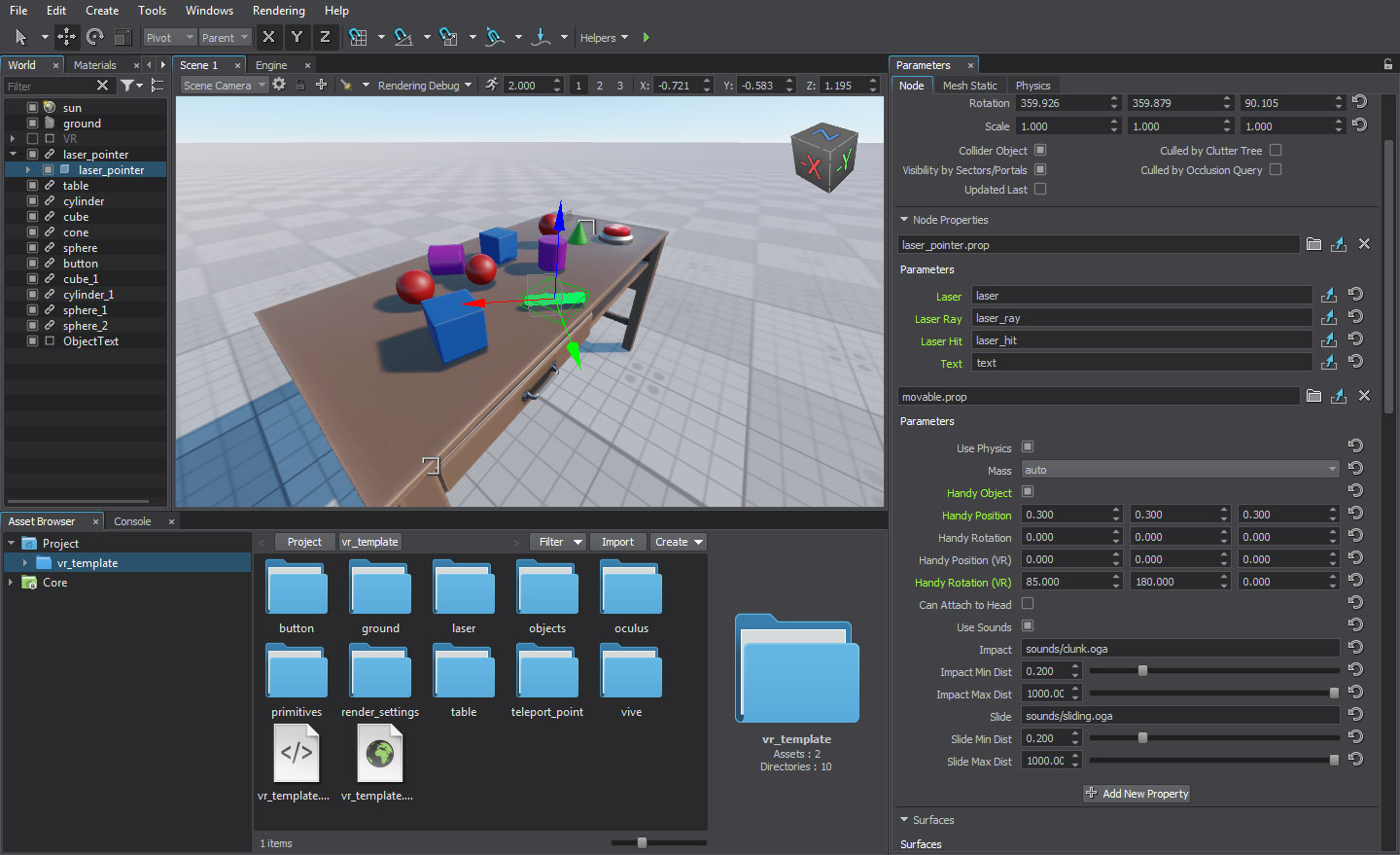
Application logic of the VR Template Demo project is now implemented using the new Component System.
For more information on the Component System please check out the sample and follow the links below:
- Component System Sample:
source/samples/Api/Logics/ComponentSystem - Custom Component System article
- Custom Component System usage example
Dynamic Destruction of Trees and Grass
Improved runtime modification of grass and clutters is now available, enabling you to modify the environment in your application – cut down trees in the forest or stamp the grass flat when driving a vehicle, simulate forest areas ravaged by fires and a lot more to add interactivity and realism to your virtual worlds.
Runtime terrain modification will give you even more power to control the environment: dig trenches or make shell craters.
You can check out some of these features in the extended Tank Demo included in all SDK editions.
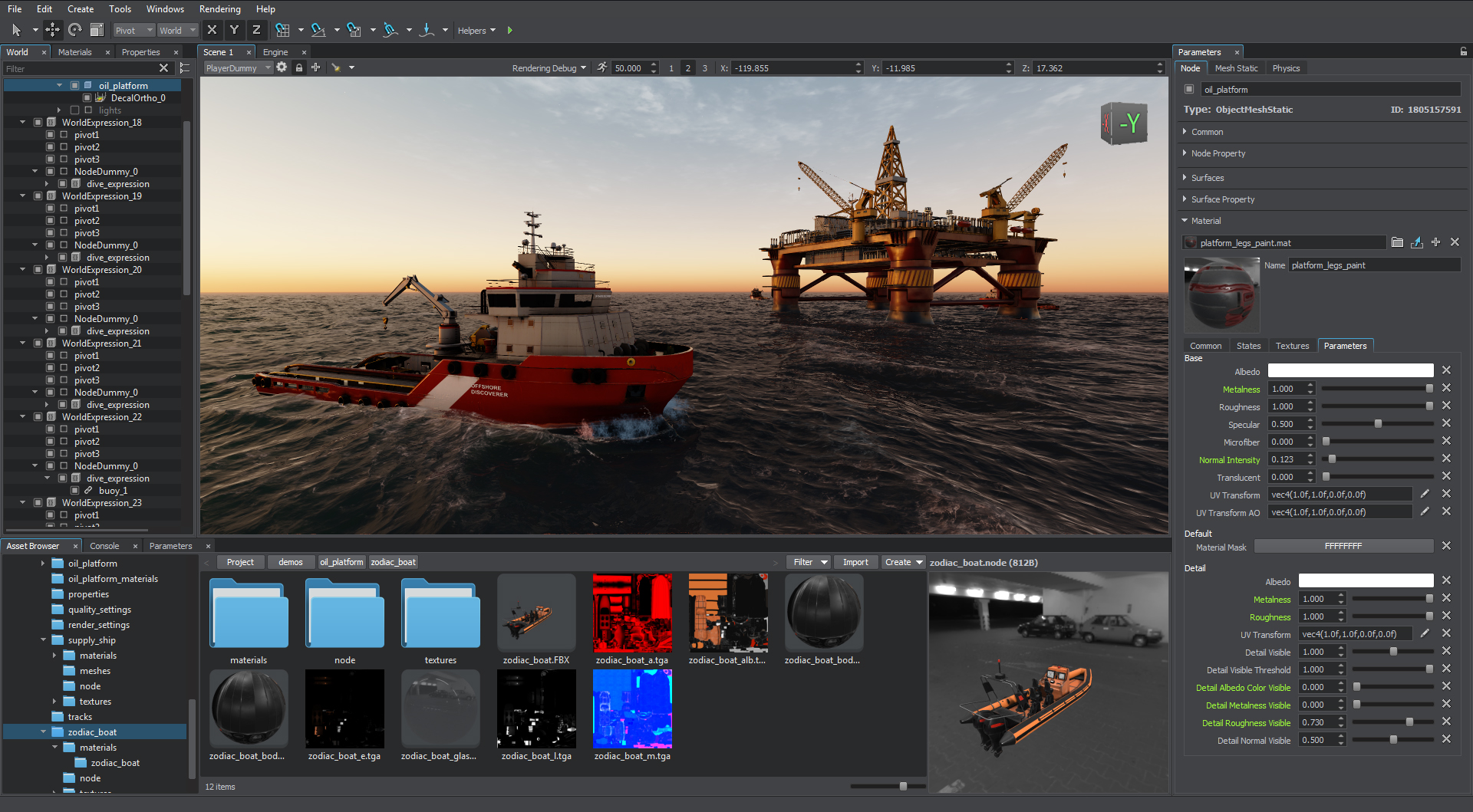
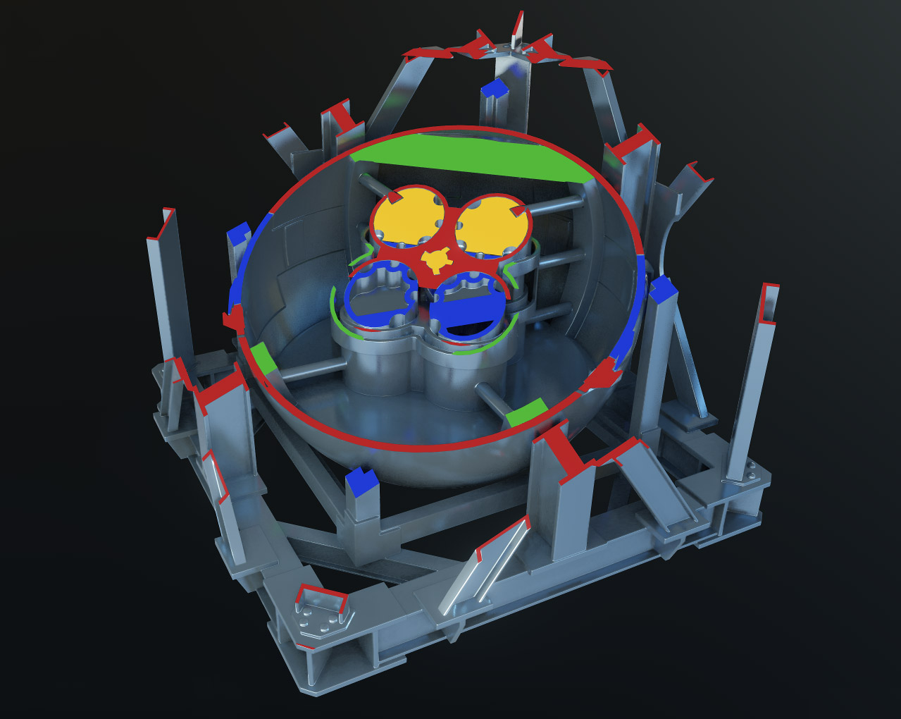
Cross Sections Visualization
Now it is possible to render cross-sections of complex CAD models. This feature is available via the new Cross Sectionstate added to the mesh_base material.
In order for cross sections to be rendered the Two Sided Common option, as well as Emission and Cross Section states must be enabled. A sample illustrating this effect called Cross_Section can be found in the Samples demo package, included in the SDK.
Improved Generation of Grass and Clutters
Added the ability to cut out the grass in the areas of intersection with objects and decals (e.g. can be used to remove grass under houses or from the surface of roads projected using decals). The grass will be cut out by objects and decals that have their intersection mask matching its Cutout Intersection bit mask (one bit at least). Cutout Inverse option allows you to determine whether the grass should be rendered inside or outside the areas determined by the cutout intersection mask. Both these options are available via the Grass tab in the Parameters window. You can also manage grass cutout via API.
The same options are available for Mesh Clutter and World Clutter objects.
Improved Anti-Aliasing
Both TAA and FXAA implementations have been improved.
Blur effect of the TAA can be significantly reduced by enabling the Fix Blur option, resulting in a sharper image. New TAA Samples and Pixel Offset parameters are available for adjustment to help you reduce flickering of small elements on the screen.
Rewritten FXAA now offers better results and can be used over the TAA to obtain even smoother image.
Both TAA and FXAA parameters can now be adjusted via the common Antialiasing section of the Rendering settings, that you can open by selecting Windows -> Settings -> Render -> Antialiasing
Screen Space Bevels
Introducing a new effect beveling edges of arbitrary geometry without the need to bake normal maps and any extra polygons. Ideally suitable for various high-poly engineering CAD models, where baking normal maps is difficult and beveling by adding more geometry is unacceptable due to a significant impact on performance. This feature can also be useful in various architectural visualization applications for buildings, furniture and other such geometry required to have smooth and neat beveling. The performance of this effect is is absolutely independent of geometry complexity. It can be adjusted per material and even modulated using a custom texture if necessary.
A sample illustrating this effect called SSBevel can be found in the Samples demo package, included in the SDK.
Terrain
As the Global Terrain object evolves and can now be generated using non-georeferenced data, the old Terrain object should be considered deprecated and will be removed in future releases.
You will not be able to create or edit a Terrain object via the Editor, as it will only be supported as a run-time object.
A migration tool is available to convert your Terrain object(s) into a Global Terrain.
ObjectTerrain to ObjectTerrainGlobal Migration Tool
Terrain Migration Tool enables you to migrate your Terrain object or multiple objects into a Global Terrain keeping all its details and visual appearance.
To perform migration do the following:
If you want to repeat migration of the ObjectTerrain(s), remove the ObjectTerrainGlobal generated during previous migration to avoid issues.
The Terrain Migration Tool produces the following folders:
- In the _migration_project folder, the generated terrain data is stored.
- In the root of the data folder, texture arrays are stored: they are copied “as is”.
- In the _terrain_migration_files folder, the data source files (height, albedo, masks sources), height and albedo textures are stored.
Migration to ObjectTerrainGlobal gives you the following advantages:
- Optimized data streaming, no more spikes
- Ability to modify your terrain via the Editor using brushes
- Ability to create limitless terrains
- Merging several old Terrain objects into a single Terrain Global object to represent large terrains
- Flexible LOD system with variable number of LODs to tune for best performance
- Support for insets, – you can create high-detail areas within the low-detail ones
- Support for triplanar and displacement mapping for more realistic visual appearance
- Ability to make the terrain curved (available in Sim edition only)
However, there are also a number of things you should be aware of:
- Shading of the ObjectTerrain and ObjectTerrainGlobal objects differs, so, their visual representation may also differ.
- LOD settings can be adjusted to increase performance.
- Some detail materials may require additional adjustment after migration: tiling of detail textures and detail masks blending should be readjusted.
- ObjectTerrainGlobal doesn’t store information about holes of the migrated ObjectTerrain.
- Current terrain modification API is a little bit more complicated, but it is currently being refactored. Improved simple and clear API will be available in the upcoming releases.
For more detailed information on terrain migration, please refer to the ObjectTerrain To ObjectTerrainGlobal Migrationsection.
Improved Terrain Material
Improved the terrain_global_base material by adding several new parameters for fine tuning of geometry optimization, shadows and LOD blending:
- Subpixel Polygons Reduction parameter determines the minimum polygon size (in the screen space) relative to the area seen in the viewport, to remove too small polygons that are barely visible, in order to increase performance.
- Back Face Culling parameter is used for culling of the tessellation patches that have their back faces turned to the camera. The number of polygons can be significantly reduced (e.g. culling back faces of a large mountain) and increase performance.
- Frustum Culling Padding parameter is used to control culling of the tessellation patches outside the viewing frustum.
- Shadow Offset parameter enables to adjust the look of shadows in cases low-poly LODs cast shadows on high poly LODs in areas, where there should be no shadows should.
- LOD Padding parameter can be used to adjust smooth transitions between terrain LODs and increase performance.
In case if your terrain does not require insets, you can disable this option to increase performance. To do so, just uncheck the Use Insets on the States tab.
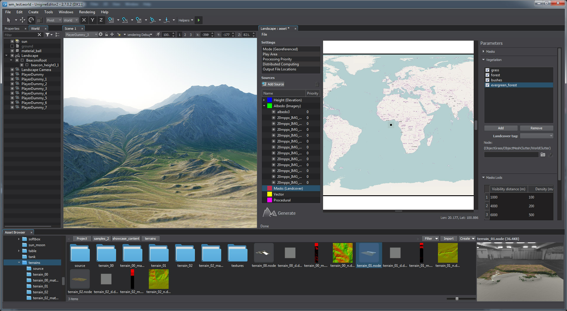
Landscape Tool
The Landscape Tool gets a new more user-friendly UI and a set of new features. Landscape Tool now allows you to generate an arbitrary terrain using non-georeferenced data, flexible procedural generation of buildings on the basis of vector data is also available.
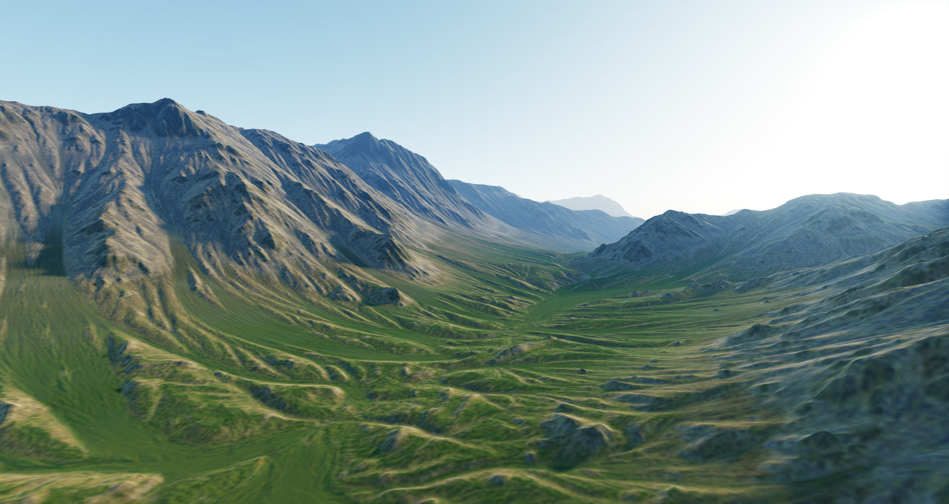
Synthetic Terrain Generation
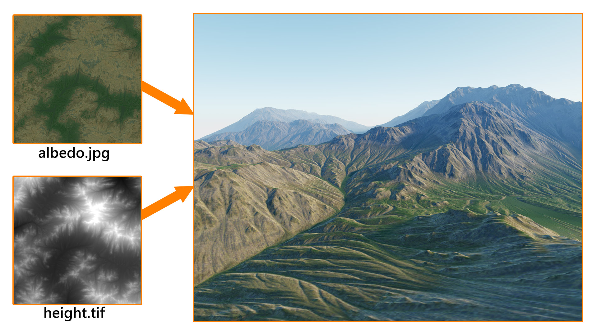
This one is really a long-awaited feature: the ability to generate an arbitrary terrain (ObjectTerrainGlobal) without georeferencing, according to your own preferences is now at your disposal!
You can now create and use any png, tif, jpg, psd, dds, tga image or a set of images (tileset) as a data source for your terrain.
To generate a terrain based on the raster images with no geodata, the Flat mode should be selected. In this mode, no reprojection is performed for the loaded data sources and terrain curving option is not available.
The Flat mode is available for all SDK versions.
You can also mix non-georeferenced data sources with georeferenced ones.
Custom Projection
Added ability to change output projection of the terrain (play area in preview map) from geodetic pivot to a custom one. This option can be used for example to match the generated landscape with existing geometry (buildings etc.) that uses custom projection.
Custom projections should be described in WKT (Well known text) format stored in .prj files. Such files can be generated by Global Mapper.
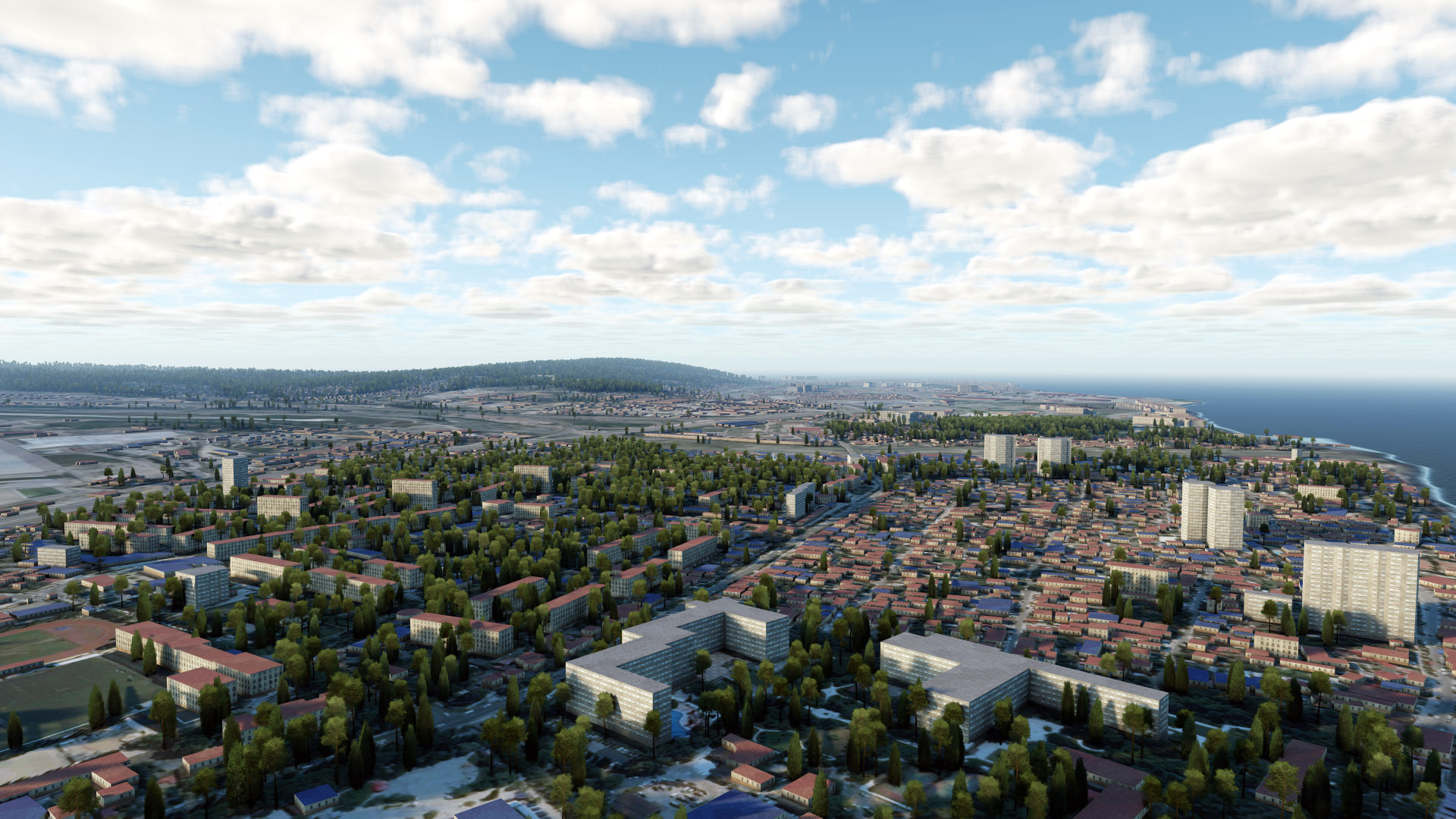
Procedural Generation of Buildings
Procedural generation of buildings on the basis of shapes contained in vector data sources (2.5D). You can specify a tag to select the data from the source and determine attributes to be used to define building category and the number of floors. You can also customize texturing of generated buildings to add more diversity and realism to the generated landscape.
For more information on procedural generation of buildings please refer to the Generating Buildings article and check out the new Procedural City Generation Demo.
You can find the full breakdown of the newest version here.